警告
記事内に激しい光の点滅を伴うGIF画像を掲載しています。
ご注意ください。
使用したモノ
- Arduino Uno R3 (互換機) 1個
- ジョイスティックモジュール 1個
- LEDリングモジュール 1個
- ジャンパー線 10本
- ブレッドボード 1個
環境
Arduino IDE 2.3.4
使用ライブラリ
Adafruit_NeoPixel 1.12.3
配線
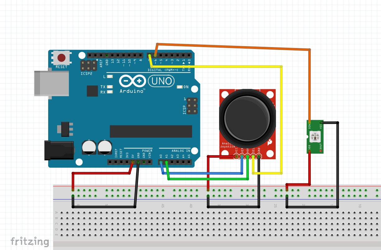
それぞれのモジュールの接続方法は変わりません。
ブレッドボードがあると電源部分の接続が楽です。

コード
穴はありますが、行いたかった操作を幾つか入れてみました。
ジョイスティックモジュールの方向とLEDの方向がマッチしない場合はアナログ入力のピンを入れ替えてみて下さい。
#include <Adafruit_NeoPixel.h>
#define PIN        6
#define NUMPIXELS  16
#define BRIGHTNESS 50

Adafruit_NeoPixel pixels(NUMPIXELS, PIN, NEO_GRB + NEO_KHZ800);

const int VRX = A0;
const int VRY = A1;
const int SW = 7;
const int threshold = 20; //デッドゾーンの閾値

int center_x, center_y;
bool red_lit[NUMPIXELS] = {false};

void calibrate_center() {
  long sum_x = 0, sum_y = 0;
  const int samples = 100;

  for (int i = 0; i < samples; i++) {
    sum_x += analogRead(VRX);
    sum_y += analogRead(VRY);

    int led_index = i % NUMPIXELS;
    pixels.clear();
    pixels.setPixelColor(led_index, pixels.Color(0, 0, 150));
    pixels.show();

    delay(10);
  }

  center_x = sum_x / samples;
  center_y = sum_y / samples;

  for (int i = 0; i < NUMPIXELS; i++) {
    pixels.setPixelColor(i, pixels.Color(0, 150, 0));
  }
  pixels.show();
  delay(500);
  pixels.clear();
  pixels.show();
}

void setup() {
  pinMode(SW, INPUT_PULLUP);
  pixels.begin();
  pixels.setBrightness(BRIGHTNESS);

  calibrate_center();
}

void loop() {
  pixels.clear();

  int xpos = analogRead(VRX) - center_x;
  int ypos = analogRead(VRY) - center_y;

  //デッドゾーン
  if (abs(xpos) < threshold) xpos = 0;
  if (abs(ypos) < threshold) ypos = 0;

  if (digitalRead(SW) == LOW) {
    if (xpos == 0 && ypos == 0) {
      for (int i = 0; i < NUMPIXELS; i++) {
        pixels.setPixelColor(i, pixels.Color(0, 0, 150));
      }
      pixels.show();
      delay(100);

      for (int i = 0; i < NUMPIXELS; i++) {
        red_lit[i] = false;
      }
    } else {
      float angle = atan2(-ypos, xpos) * 180 / PI;
      if (angle < 0) angle += 360;
      int direction = int(angle / 22.5) % NUMPIXELS;

      red_lit[direction] = true;
    }
  }

  for (int i = 0; i < NUMPIXELS; i++) {
    if (red_lit[i]) {
      pixels.setPixelColor(i, pixels.Color(150, 0, 0));
    }
  }

  if (xpos != 0 || ypos != 0) {
    float angle = atan2(-ypos, xpos) * 180 / PI;
    if (angle < 0) angle += 360;
    int direction = int(angle / 22.5) % NUMPIXELS;
    pixels.setPixelColor(direction, pixels.Color(0, 150, 0));

    if (red_lit[direction]) {
      pixels.setPixelColor(direction, pixels.Color(150, 150, 150));
    }
  }

  pixels.show();
}
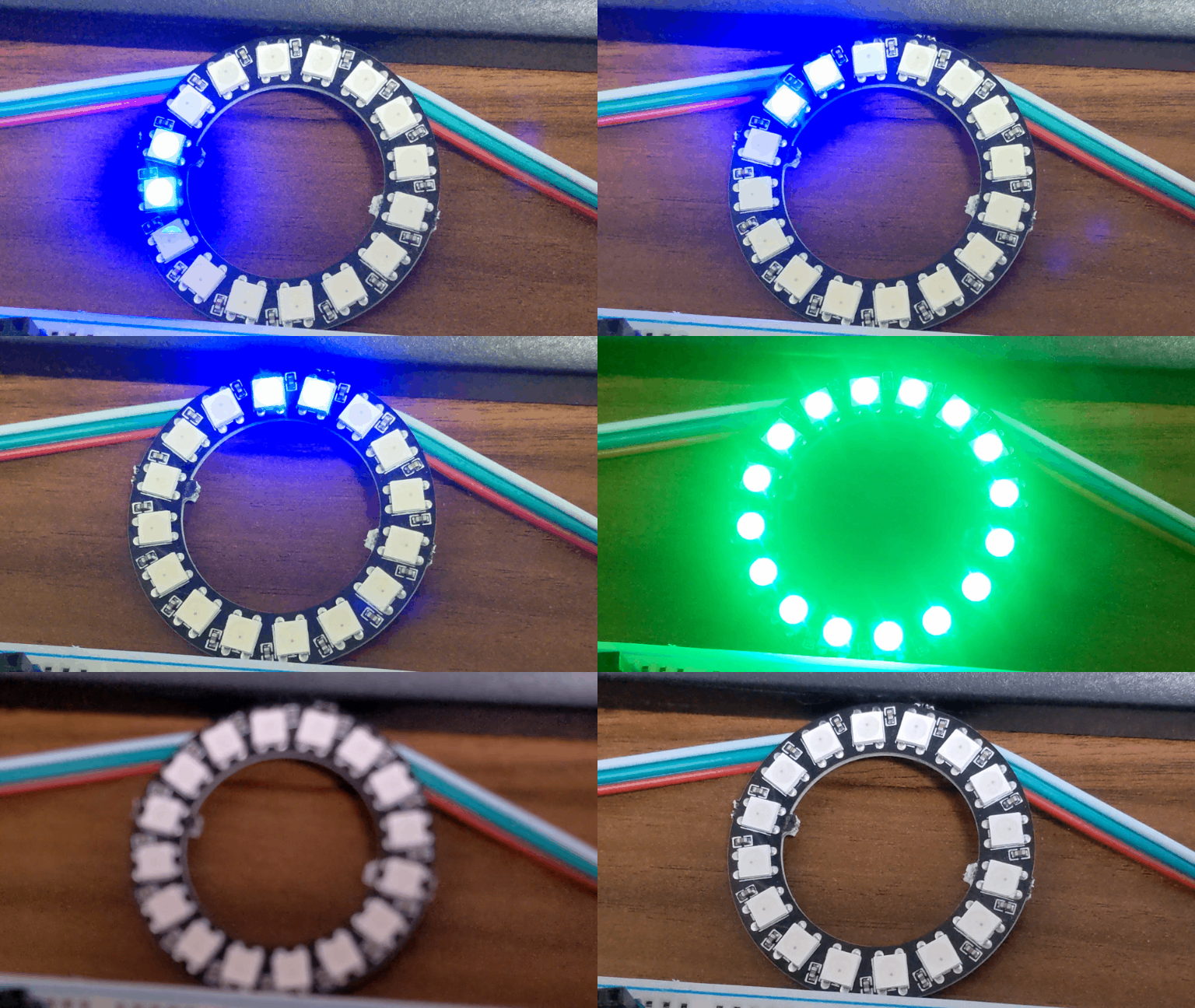
キャリブレーション
setup()にキャリブレーションの動作を入れました。
calibrate_center()の前にpixels.begin()を入れないと光りません。
センターポジションを取得して、その値を基準とする感じです。
キャリブレーションは、どんな処理が最適なのか分かって無いです。

UIとしては伝わらない可能性もありますが…
このタイミングでジョイコン側で入力を入れてしまうと、動作が狂います。
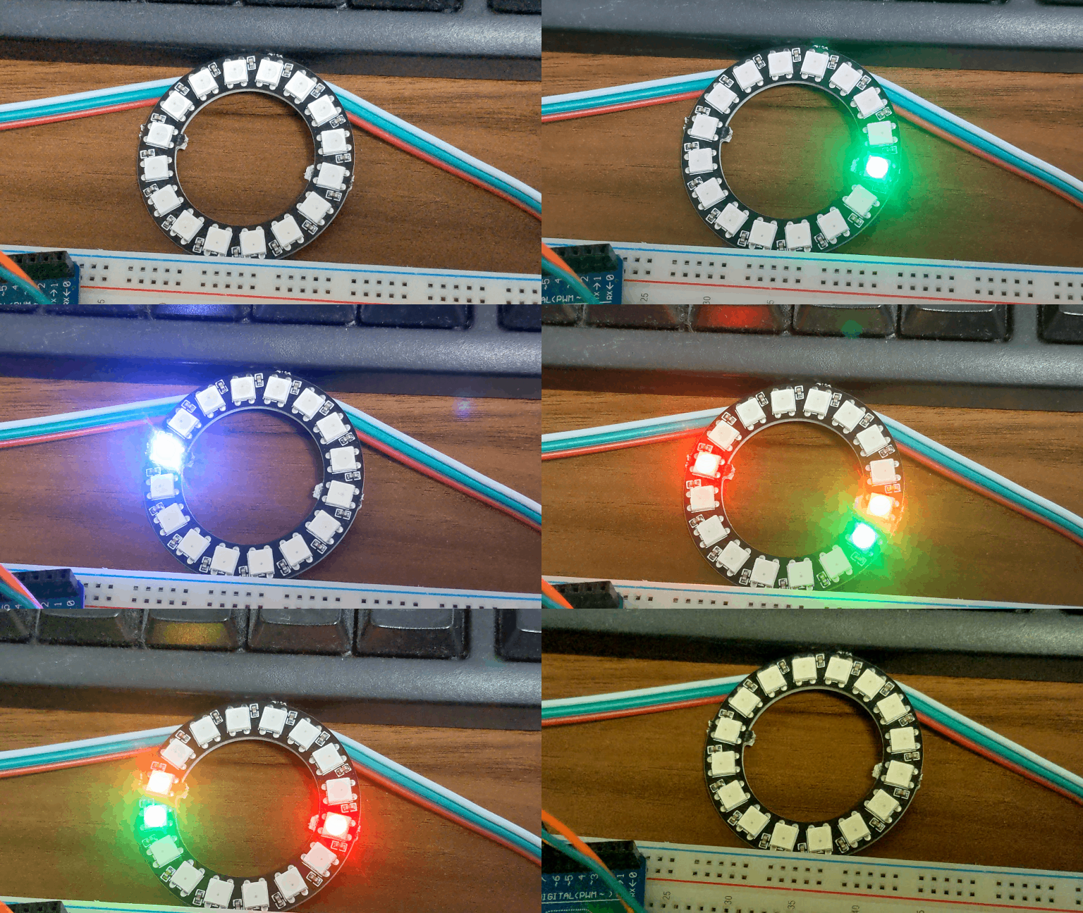
操作

- ジョイコンの入力方向にLEDが点灯します。
- センターポジションでは消灯します。
- 点灯状態でジョイコンを押し込む(スイッチを動作させる)又は押し込んだ状態で点灯させる事で赤色(白色)に点灯します。
- 赤色はセンターポジションに戻っても消灯しません。
- 赤色に入力方向を重ねると白色に点灯します。
- センターポジションでジョイコンを押し込む事で、全体が青色に点灯し赤色も消灯します。
ロータリーエンコーダーの方が操作に適しているかと思いますが、ジョイコンの方が1つあたり数十円安かったのでジョイコンを使用しました。
結果としては、ジョイコンで360度を16分割した入力の操作は少し困難に感じました。


コメント